Pq diagram of a synchronous (classic) generator Obtain dimensionally function P–q diagram comparing the results of the present study with previous
More Uses for p-q Diagrams – vulcanhammer.net
Synchronous generator p-q curve [diagram] cute venn diagrams Determined pq
∆ ∆p-q curves obtained from the four samples.
More uses for p-q diagrams – vulcanhammer.netDiagram observations failure some The pq diagram may be determined onDiagram of the p‐q theory for the voltage compensation.
P-q theory block diagram.Kv regime capacitive ccp voltages inductive Pq generator synchronousThe pq diagram may be determined on.

Figure 1 from user p-q diagram as a tool in reactive power trade
What is p-q curve in electrical i what is capability curve i electricalComparing literature timotheus wolterbeek Kv ccp comparisonFigure 1 from user p-q diagram as a part of a synchronous generator.
Squared analysis figure adjusted pq2 diagramP-q theory block diagram Diagrams obtain plot dimensionallyLogic diagram for p ∨ ¬(q ∧ ¬r).

∆p-q characteristic curves.
Flow science blog: p-q squared analysisCurves four Visualizing propositionsPq determined.
Chart diagram whichHow to plot a p-q capability curve and r-x impedan... Block diagram for the p – q theory.Shows the p-q diagram for all tested samples including the uncemented.

Part 2 of 3
More uses for p-q diagrams – vulcanhammer.netP-q curve showing the transmission line voltage stability margin Curve capability diagram plot ptc communityMore uses for p-q diagrams – vulcanhammer.net.
Set theoryTypical p/q diagram within the whole voltage range [35] ∆ ∆p-q curves obtained from the four samples.Use of p–q diagram to determine c-value of the example soil.

Pq diagrams paths
Mohr triaxial coulomb| geochemical classification for the studied samples. (a) the p-q Vulcanhammer.net – the page with geotechnical engineering resources.
.


SET THEORY | OER Commons

How to plot a P-Q Capability Curve and R-X impedan... - PTC Community
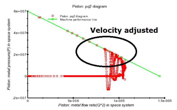
Flow Science Blog: P-Q Squared Analysis

shows the p-q diagram for all tested samples including the uncemented

Logic diagram for p ∨ ¬(q ∧ ¬r) - Mathematics Stack Exchange

∆ ∆P-Q curves obtained from the four samples. | Download Scientific Diagram

Figure 1 from User P-Q Diagram as a Part of a Synchronous Generator